A wall can look fine in the warehouse and fail as soon as it reaches a ballroom, arena floor, or broadcast position. A row of dark pixels, a color shift across one cabinet, intermittent signal loss, or a panel that drops out after warmup can put a production team under immediate pressure. Effective on site LED troubleshooting is not about swapping the first suspect module. It is about isolating the actual failure point before a minor defect becomes an avoidable show risk.
For professional LED operators, the visible symptom is rarely the whole story. A dead section may be caused by a damaged module, but it can also trace back to a receiving card, a ribbon cable, a power distribution issue, a failed driver IC, a processor setting, a mapping error, or damage from prior handling. The repair decision needs to reflect what the display is doing, what the system has experienced, and how quickly it must return to professional service.
Start With the Failure Pattern, Not the Spare Parts
A useful first step toward a correct repair is to document the failure before anything is removed. Ask when the problem appears, whether it follows a specific cabinet position, and whether it changes after the wall has been powered for a period of time. A panel that fails only after heat buildup points to a different set of causes than one that remains dark from power-up.
A clear failure pattern narrows the field. A single dead pixel or small cluster may indicate LED package damage, a solder joint issue, or a failing driver channel. A repeated vertical or horizontal line can suggest a driver IC, scan circuit, data path, or PCB issue. A full module with no output can be a local power, data, or module-level failure. If several cabinets show the same behavior, the problem may be upstream in the signal chain rather than inside every affected panel.
This distinction matters when managing rental inventory or a permanent installation. Replacing several modules may make the wall look better temporarily, but it does not solve a processor configuration error, a bad output port, or an intermittent data cable. It also creates unnecessary cost and can introduce brightness or color variation if replacement modules do not match the existing batch and calibration state.
Verify the Signal Chain Before Opening Cabinets
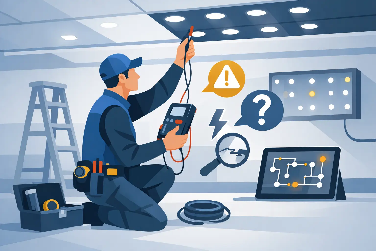
A disciplined on-site LED troubleshooting process begins at the system level. Confirm the source output, processor configuration, output mapping, cable routing, receiving-card status, and cabinet power. Review whether the display has been moved, reconfigured, or updated since it last operated correctly. Those details often help explain a fault that initially appears to be hardware-related.
Test known-good signal paths where practical. Move the suspected cable, output, or receiving card position and observe whether the failure moves with it. If it does, the fault is likely upstream or tied to that component. If the problem stays with the same physical module or cabinet, the investigation can move deeper into the display hardware.
This is especially important with intermittent issues. A connector can pass a quick continuity check and still fail under vibration, load, or repeated thermal cycles. Likewise, a processor can deliver a stable test pattern while a live input exposes scaling, frame rate, EDID, or sync-related behavior. Testing should reflect the operating conditions that created the original failure whenever practical.
Inspect the Cabinet as a Working System
Once the issue is contained to a cabinet, inspection should not stop at the visible LED face. Technicians should examine module connections, ribbon cables, power and data connectors, receiving cards, cable strain, locking hardware, and signs of impact or moisture exposure. Bent pins, partially seated connectors, crushed ribbon cables, and damaged mounting points can create failures that come and go with cabinet flex.
Power conditions deserve the same attention. Low or unstable voltage can cause dim output, flicker, random resets, and partial module failures that resemble a bad panel. A cabinet may power on normally at idle but become unstable at higher brightness or during a white-field test. Measuring under appropriate operating load can help distinguish a power-delivery issue from a module defect.
Visual inspection also provides context for repairability. A clean, isolated component failure may be a strong candidate for component-level repair in a controlled repair environment. A heavily corroded board, burned PCB trace, or cabinet with extensive impact damage may require a different recommendation. There is no value in forcing a repair when the condition of the equipment does not support an appropriate return to service.
When Module Swapping Helps and When It Hides the Problem
Swapping a known-good module into the suspect location is useful as a diagnostic step. If the replacement works correctly, the original module deserves closer evaluation. If the replacement shows the same fault, the issue may be in the cabinet data path, power delivery, receiving card, or configuration.
The trade-off is that repeated swapping can spread uncertainty or erase useful evidence. A module that was removed without documenting its original position, symptoms, and test result becomes harder to evaluate later. For large inventories, this creates a cycle of “bad” panels moving from case to case without a confirmed diagnosis.
A better process is to label the cabinet, module position, and failure condition, then record what changed after each test. This is not paperwork for its own sake. It helps protect the team from reinstalling an unresolved module before a show and gives the repair technician enough information to reproduce the problem accurately.
Component-Level Diagnosis Changes the Replacement Decision
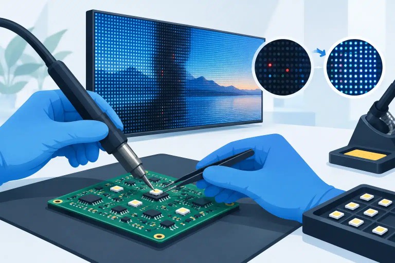
Professional LED modules are not automatically disposable simply because a few pixels have failed. Many defects originate at the component level: failed LEDs, damaged driver ICs, broken data traces, compromised passive components, cold solder joints, or PCB damage caused by impact and handling. With the right diagnostic equipment, controlled repair methods, and precision soldering process, many localized failures can be evaluated for component-level repair without replacing the entire module.
That does not mean every module should be repaired. Replacement may be the better choice when the module is obsolete, significantly damaged, difficult to match visually, or not economically practical to restore. The point is to make that decision from verified findings, not from a visual guess or a blanket rule.
For AV companies and venues, the practical value is control. A properly evaluated and repaired module can help preserve inventory, reduce pressure on spare stock, and maintain display consistency when matching replacements are difficult to source. It can also reduce unnecessary disposal of panels that may still have useful service life.
Test for the Conditions That Cause Real Failures
A repair is not complete because the pixels illuminate on a bench. The module or cabinet should be tested for correct color response, brightness behavior, data stability, scan performance, and operation through appropriate patterns. Full-white, grayscale, red, green, blue, black, and moving-content tests each reveal different problems.
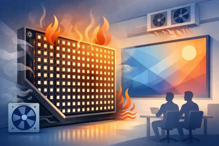
Thermal behavior matters as well. Some faults appear only after the board reaches operating temperature. Others emerge when a cabinet is run at higher brightness or receives sustained data. Final testing should be appropriate to the reported failure and intended application, particularly for equipment headed back into rental inventory or a high-visibility installation.
Documented QC provides accountability here. The record should identify what was found, what was repaired or replaced, and how the unit performed in final testing. For a technical director or inventory manager, that documentation makes it easier to decide where the unit can be deployed and what follow-up, if any, is required.
Know When to Escalate the Fault
Field teams can resolve many issues through controlled signal checks, cable replacement, configuration verification, and cabinet-level isolation. But recurring defects, PCB damage, failed ICs, persistent color inconsistencies, and unexplained intermittent problems may require a controlled repair environment with microscope-level inspection and component-level tools.
That is where a specialized technical repair partner adds value. With more than a decade of technical service experience in professional LED environments, 725Co. evaluates the actual failure rather than treating every symptom as a module replacement. The goal is a quality-focused repair supported by documented QC, not a quick fix that returns during the next rental, event, or operating cycle.
The best time to address a questionable module is before it becomes the one cabinet that fails in front of a client. Clear diagnostics, controlled testing, and repair decisions based on evidence give LED inventory a stronger basis for returning to professional service before the next deployment.

Jose de Jesus Martinez (Chuy) is the CEO of 725co. LED Repair Professionals, a trusted name in high-quality LED module repair and video wall services. With over 12 years of experience and certification as an electronic engineer, Chuy has built a reputation for excellence, partnering with industry leaders. Under his leadership, 725co is known for precision repairs, transparent service, and a commitment to protecting the long-term value of LED investments.