A module that drops signal, shows intermittent rows, shifts color, or fails after transport is often labeled a bad panel. Sometimes it is. But LED connector repair can be the more accurate answer when the actual failure sits at the connection between the module, hub board, receiving card, or cabinet wiring. Replacing a module without confirming that path can put a working part into a cabinet that still has the same underlying fault.
For rental houses, production teams, integrators, and venue operators, that distinction matters. A connector problem can create a failure that appears only when a cabinet is flexed, after it reaches operating temperature, or when a specific module position is used. Those are difficult conditions to diagnose from a quick visual inspection, and they can lead to repeated repairs, unreliable inventory, and avoidable replacement costs.
What LED Connector Failures Actually Look Like
Professional LED systems use several connection points to distribute power and data through a cabinet. Depending on the display architecture, those may include module-to-hub connectors, ribbon cables, board headers, receiving card connections, power plugs, and inter-cabinet signal connections. A fault at any point can mimic a much larger problem.
The symptom does not always point directly to the failed component. A poor data connection may present as random pixel behavior, a missing section of image, scan-line issues, or intermittent blackouts. A compromised power connection can cause dimming, unstable brightness, flicker under load, or a module that comes and goes. Bent pins, cracked solder joints, heat-damaged housings, oxidized contacts, damaged cable conductors, and lifted pads on a PCB all require different corrective action.
Physical damage is only part of the picture. Repeated installation and removal, vibration during transport, cabinet impact, cable strain, moisture exposure, and prior repair work can all compromise a connection. In a high-use rental environment, a connector may look acceptable until it is placed under normal electrical load or subjected to the movement it sees in the field.
This is why an intermittent fault deserves more than a basic swap test. Swapping modules can help isolate a symptom, but it does not prove the removed module is defective. If the issue remains in the same cabinet position, follows a cable path, or returns when the cabinet is assembled, the connector and supporting circuitry need closer examination.
LED Connector Repair Starts With Fault Isolation
A reliable repair process begins by defining the failure clearly. Is the issue limited to one module position? Does it follow the module when moved? Does it appear at a particular brightness level, refresh setting, temperature, or cable orientation? Is the fault repeatable after reassembly?
Those questions prevent an expensive and common mistake: treating a symptom as a diagnosis. A dead pixel may be a failed LED, driver IC, trace, connector pin, or data-path issue. A black module may have a module fault, but it may also be receiving incomplete power or signal. The repair path changes completely once the true point of failure is identified.
A proper inspection typically includes checking the connector condition, mating force, pin alignment, cable integrity, solder joints, PCB pads, adjacent traces, and the behavior of the circuit under test. For fine-pitch and professional display hardware, microscope-level examination often reveals damage that is not visible from the cabinet face or with a quick continuity check.
Signal and power paths should be tested in context. A connector can pass a simple static test while failing under load, during vibration, or after thermal expansion. Technicians also need to consider the connected equipment. A damaged hub board, receiving card output, or incorrectly seated ribbon cable can create the same symptoms as a failed module connector.
When Cleaning Is Not a Repair
Contamination on contacts can affect performance, particularly in environments with dust, moisture, haze residue, or frequent handling. Careful cleaning may be appropriate when the connector itself is undamaged and the problem is clearly related to surface contamination.
Cleaning is not a cure for deformed contacts, burned terminals, loose headers, cracked solder joints, damaged plating, or lifted PCB pads. Forcing a compromised connector back into service can worsen the damage and create a fault that is harder to isolate later. The correct response may be connector replacement, cable replacement, board-level repair, or replacement of the affected assembly when the damage is too extensive to repair reliably.
Repairing the Connection Without Creating a New Failure
Connector work on LED display hardware is precision work. Heat must be controlled, the correct replacement component must be selected, and nearby pads, traces, LEDs, and integrated circuits must be protected. The goal is not merely to restore continuity. It is to restore a mechanically sound, electrically stable connection that can tolerate normal use.
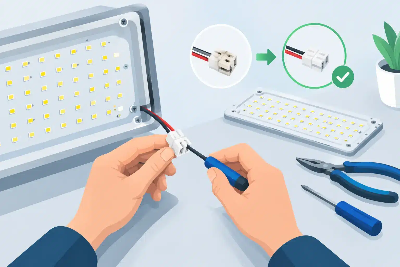
For a damaged board-mounted connector, component-level repair may involve removing the failed connector, preparing the pads, rebuilding damaged traces or pads where practical, installing the replacement, and inspecting every joint under magnification. If the failure is a cable or ribbon assembly, replacement may be the better decision, especially when conductors have been stretched or insulation has been compromised.
There are trade-offs. A repairable connector on an otherwise healthy module or hub board can be a practical way to preserve valuable inventory. However, a board with extensive heat damage, multiple lifted pads, corrosion, or previous unsuccessful repair attempts may not be a good candidate for return to demanding service. The right decision depends on the display model, part availability, repairability, the role of the cabinet in the system, and the operational risk of putting marginal hardware back into rotation.
This is particularly relevant for matched LED walls. Replacing a module can introduce calibration, color, brightness, or batch-matching concerns. Repairing the actual connection issue may preserve the original module and reduce the need to introduce a replacement part that requires additional calibration or does not match the wall as expected.
Testing Must Match Field Conditions
A connector repair is not complete because the display lights up on the bench. Professional LED equipment must be evaluated for stable power delivery, reliable data transmission, correct image behavior, and repeatable performance after the hardware is handled and reassembled.
Final testing should verify that the repaired location operates correctly alongside the related modules, hub board, and controller path. Depending on the fault, that can include visual inspection, continuity checks, power verification, signal testing, image pattern testing, color and brightness observation, and extended operation. A repair that survives only a brief power-on test may still fail during a show, a load-in, or the next rental cycle.
Documented quality control gives operations and technical teams useful information beyond a simple pass or fail. It establishes what was found, what was repaired or replaced, and how the equipment performed during final testing. That record helps when a cabinet has a history of intermittent problems, when inventory is being triaged, or when a team needs to distinguish a repaired fault from a separate issue that develops later.
At 725Co., connector-related issues are evaluated as part of the complete module and cabinet signal path, not as isolated cosmetic damage. That component-level approach is designed to identify the real source of failure and return equipment to service with repair documentation and final QC.
Preventing Repeat Connector Problems
Not every connector failure is preventable, but handling practices make a measurable difference. Cable strain relief should be maintained, connectors should never be forced into misaligned headers, and damaged or bent pins should be addressed before they damage the mating side. Cabinets that experience regular transport benefit from inspection at the same time technicians check latches, corners, power distribution, and module mounting.
Recurring failures in the same location deserve attention even if a temporary module swap restores the image. The pattern may point to cabinet flex, a stressed cable route, a loose board, a marginal power connection, or a receiving card output issue. Tracking that history helps prevent a cabinet from becoming an unreliable piece of inventory that only fails after it reaches a job site.
When a display fault appears, the practical question is not simply whether a module can be replaced. It is whether the system has been diagnosed well enough that the repair will hold when the wall is back under real operating pressure.

Jose de Jesus Martinez (Chuy) is the CEO of 725co. LED Repair Professionals, a trusted name in high-quality LED module repair and video wall services. With over 12 years of experience and certification as an electronic engineer, Chuy has built a reputation for excellence, partnering with industry leaders. Under his leadership, 725co is known for precision repairs, transparent service, and a commitment to protecting the long-term value of LED investments.