

A video wall can look fine in the warehouse and develop problems the moment it is loaded into a show file, pushed to higher brightness, or installed in front of a client. Component level video wall repair is built for that reality. It goes beyond replacing an entire module because a few pixels are dark, a color channel is unstable, or an image artifact appears under load. The goal is to identify the actual failure, correct it at the board level when appropriate, and return the asset with documented evidence of how it performed during final testing.
For rental houses, AV integrators, production teams, and venue operators, this is not a cosmetic issue. A bad module can compromise a camera shot, delay a load-in, reduce available rental inventory, or create an expensive last-minute replacement decision. Proper repair helps protect both presentation quality and operational flexibility.
What Component-Level Video Wall Repair Actually Means
Component-level repair focuses on the individual electronic parts that make an LED module function. Depending on the failure, that can include LEDs, driver ICs, resistors, capacitors, connectors, signal paths, power circuits, pads, traces, and other PCB-level components. A technician uses visual inspection, electrical testing, signal analysis, and microscope-level soldering to isolate the defective part or damaged area.
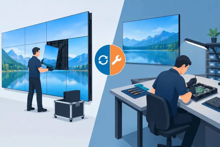
That approach differs from module swapping. Replacing a module is sometimes the right call, especially when a matching, properly configured replacement is available and the damaged unit has little practical repair value. But a replacement module may be discontinued, delayed, difficult to color-match, or too costly to use as the default answer for every fault. In a large inventory, repeatedly removing repairable modules from service can also create an avoidable supply problem.
The practical value is diagnosis. A module with a vertical line may have a failed driver IC, but it could also have a damaged connector, a broken trace, a receiving-card configuration issue, or a problem upstream in the cabinet. Replacing parts before identifying the failure can waste time and introduce a second problem.
Why Professional LED Walls Need a Different Repair Standard
Professional LED systems operate under conditions that can expose weak repairs quickly. Rental modules are moved, stacked, transported, assembled, and disassembled. Touring systems experience vibration and connector wear. Permanent installations may run long hours at demanding brightness levels. Heat, power quality, handling damage, moisture exposure, and prior repair work can all affect performance.
A repair that merely lights the affected pixels is not necessarily a complete repair. The repaired section should perform consistently with the rest of the module. That means checking color behavior, grayscale response, brightness consistency, refresh stability, scan operation, and physical integrity. On fine-pitch products, even minor inconsistencies can be visible from normal viewing distances or amplified by broadcast cameras.
Professional LED repair also requires considerations that go beyond typical consumer electronics work. Professional operators need repairs that account for module mapping, calibration, signal behavior, cabinet fitment, and the conditions in which the product will actually be deployed.
The Failures That Require Real Diagnosis
Dead pixels are the most obvious symptom, but they are only one category. A single failed LED can be a localized component issue. A cluster of failed pixels may point to a driver IC, power circuit, or signal path. Intermittent pixels can be even more difficult because they may appear only after the module warms up, flexes in a cabinet, or receives a specific data pattern.
Color failures require similar care. A red, green, or blue channel that is missing or weak may originate at the LED package, but it can also result from a failed output on a driver IC or damage to the PCB. A module that displays random flashing, ghosting, horizontal artifacts, or unstable sections may have a signal integrity issue, a connector problem, damaged data lines, or a configuration fault rather than a simple pixel failure.
Not every apparent module failure is a module failure. Poor power distribution, a failing hub board, a receiving card problem, incorrect firmware, processor settings, or mapping errors can produce symptoms across multiple modules. Before sending a wall full of panels for repair, it is worth documenting what happens when the issue follows a module, a cabinet position, a signal output, or a power feed. That information helps shorten the diagnostic path.
Damage From Previous Repair Attempts
Some of the most time-consuming cases begin with a repair that was attempted without the appropriate tools or process. Lifted pads, overheated LEDs, bridged pins, incorrect replacement parts, contaminated solder joints, and damaged traces can turn an isolated failure into a broader board-level problem.
A quality-focused repair partner should be able to distinguish the original defect from damage introduced later. That matters for making an informed repair-versus-replace decision and for reducing the chance that the same module returns with a recurring issue.
A Repair Process That Protects Uptime
The work should begin with intake documentation. Record the module type, pixel pitch, known symptoms, cabinet location if available, and any prior service history. Clear photos and a description of the test conditions help establish whether the fault is constant, intermittent, heat-related, or dependent on a particular signal source.
Next comes controlled testing. Technicians inspect the module under magnification, test power and data paths, run suitable patterns, and isolate the affected circuit. If the issue is repairable, the damaged component is removed and replaced using precision soldering methods appropriate to the board and component package. Trace or pad repair may be needed when physical damage extends beyond the original part.
After the repair, the module should not be treated as complete simply because it powers on. It may require extended functional testing where the failure mode calls for it, along with checks for pixels, color, scan behavior, image stability, and connection integrity. Final inspection should also confirm that the repair does not interfere with module fit, magnets, masks, connectors, or service access.
At 725Co., this process is centered on component-level diagnostics, professional soldering standards, and documented QC. With more than a decade of technical service experience supporting professional LED environments, the emphasis is on returning equipment with a well-supported basis for working inventory, not simply passing a quick bench test.
When Repair Makes Sense and When Replacement Is Better
Component-level video wall repair is not a blanket recommendation. The appropriate decision depends on the module’s condition, product lifecycle, availability of matched replacements, extent of PCB damage, and the operating requirements of the client.
Repair is often practical when the module is otherwise healthy, the fault is localized, replacements are scarce, or maintaining the existing module set is important for color and calibration consistency. It can also be valuable when a client needs to recover usable inventory without waiting for extended replacement lead times.
Replacement may be the better choice when corrosion is widespread, the PCB is heavily damaged, the module has repeated unrelated failures, or a compatible replacement can be installed and calibrated without creating a visible mismatch. For aging product lines, the decision may involve a broader inventory strategy: repair modules that can appropriately return to service, reserve matched spares for high-visibility deployments, and retire units that have reached the point of diminishing returns.
The key is avoiding false economy on either side. Automatically replacing every faulty module can be unnecessarily expensive. Repairing a severely compromised module simply because it is technically possible can create future downtime. A well-supported technical assessment gives operations and purchasing teams the information needed to make an informed decision.
What to Send With a Failed Module
A more efficient repair path starts before the equipment arrives. Include the module model, serial information when available, a clear description of the symptom, and photos or video of the fault. Note whether the issue appears on all inputs, changes after warm-up, follows the module to another cabinet, or occurs only in a specific position.
For recurring issues, include a short history. If the module has already been repaired, if the cabinet suffered impact damage, or if the wall experienced a power event, that context matters. It can point the technician toward the likely failure mechanism and help identify conditions that a single static test may not reveal.
Better Repair Decisions Start With Better Evidence
A failed LED wall module puts pressure on everyone involved, from the technician building the wall to the project manager responsible for a clean client presentation. A useful response is not guesswork or a rushed swap based only on what is visible from the front of the screen. It is a documented diagnosis that separates a repairable component fault from a system-level issue or a module that has reached the end of its practical service life.
That level of evidence helps teams deploy with more confidence, preserve valuable inventory, and make replacement decisions on their terms rather than during the next emergency.

Jose de Jesus Martinez (Chuy) is the CEO of 725co. LED Repair Professionals, a trusted name in high-quality LED module repair and video wall services. With over 12 years of experience and certification as an electronic engineer, Chuy has built a reputation for excellence, partnering with industry leaders. Under his leadership, 725co is known for precision repairs, transparent service, and a commitment to protecting the long-term value of LED investments.

4 Responses