

A panel that looks acceptable in the shop can still fail when it is part of a full wall, driven at show brightness, and running for hours. That is why knowing how to test LED panels is not just about finding dead pixels. For rental inventory, permanent installations, and event systems, proper testing helps confirm whether a panel is electrically stable, receiving clean data, matching the wall, and performing appropriately under operating conditions.
The goal is to isolate the actual source of a fault before swapping parts or declaring a panel bad. A black section may be a module, ribbon cable, power supply, receiving card, HUB board, processor setting, or data-path issue. A disciplined test process helps prevent unnecessary replacement costs and reduces the chance of sending a questionable panel back into service.
Start With a Controlled Test Environment
Test panels on a known-good system whenever possible. Use a verified power cable, signal cable, processor output, receiving-card configuration, and adjacent known-good panels. If several unknown components are introduced at once, the result can be difficult to interpret.
Before applying power, inspect the cabinet and module faces under good light. Look for impact damage, lifted LEDs, cracked masks, bent connectors, corrosion, liquid residue, heat discoloration, and prior solder work. On rental panels, pay close attention to corner damage, magnet alignment, module seams, and connector strain. A panel may operate on the bench while mechanical damage creates intermittent faults during transport or wall assembly.
Confirm that the test setup matches the panel’s specifications. Incorrect voltage, an incompatible receiving-card file, or wrong scan settings can create symptoms that look like a failed module. Professional LED systems are not interchangeable by default, even when two cabinets appear similar.
How to Test LED Panels for Power and Signal Faults
Power and signal should be evaluated before pixel-level repair decisions are made. Start by checking whether the cabinet powers consistently and whether all internal power supplies are producing the correct output under load. A supply that reads correctly with no load can still sag when the panel displays a high-brightness white image.
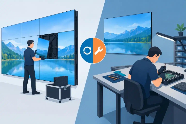
With the panel connected to a known-good signal path, verify that it initializes correctly and appears in the expected position within the wall. Then move the suspect cabinet to a location occupied by a known-good cabinet. If the fault moves with the cabinet, the issue is likely inside that cabinet. If it stays in the same wall position, investigate the incoming data cable, output port, processor configuration, or previous cabinet in the signal chain.
This simple substitution test can save time. It helps separate cabinet failures from system failures without relying on assumptions.
A complete black cabinet does not automatically mean no power. Some panels have active power but no valid data, while others can lose one voltage rail and produce partial or unstable output. Check power distribution, fuses, connectors, receiving-card status indicators, HUB board connections, and data jumpers. Do not repeatedly power-cycle a cabinet with visible overheating, burning odor, or damaged circuitry. That can increase the extent of an existing board-level problem.
Use Test Patterns That Expose Real Defects
A full white screen is useful, but it should not be the only test. Run controlled test patterns at the intended operating brightness and observe the panel from normal viewing distance and close range. Solid red, green, and blue patterns expose weak or failed subpixels. Black patterns reveal unintended glow, leakage, and stuck pixels. Gray patterns are especially valuable because they reveal low-gray inconsistency, scan-line issues, and calibration mismatch that can disappear under brighter content.
Use moving and changing content as well. Some faults only appear during data transitions, high refresh operation, or video playback. Watch for flicker, horizontal or vertical lines, blocky artifacts, ghosting, intermittent rows, and color shifts that appear after several minutes.
The most useful pattern sequence includes:
- Full red, green, blue, white, and black fields
- Low-gray steps to identify dim pixels and uneven grayscale
- A fine grid or checkerboard pattern for alignment and scan problems
- Motion content for flicker, tearing, and intermittent data faults
- High-brightness white for increased power and thermal load
Document what appears, where it appears, and whether it changes with brightness, temperature, cable movement, or cabinet location. A clear fault record gives a technician much more useful information than a note that simply says, “panel is bad.”
Check Color, Brightness, and Calibration Match
A repaired or replacement panel can be electrically functional and still be unsuitable for a client-facing wall. Compare it to adjacent cabinets using white, gray, and primary-color patterns. Look for differences in color temperature, brightness, gamma response, black level, and module-to-module uniformity.
This matters most on camera-facing displays, corporate walls, retail installations, broadcast environments, and premium event inventory. A slight green cast or a visibly darker module may be acceptable for a back-of-house spare, but not for a main wall in front of an audience or client camera.
First confirm that the correct calibration data and receiving-card configuration are loaded. If the configuration is correct and the mismatch remains, the cause may be aging LEDs, a defective driver IC, incorrect module batch, damaged calibration data, or a prior repair that did not account for optical performance. Calibration can improve consistency, but it cannot correct every hardware defect.
Test Under Load and Over Time
Many LED failures are intermittent. A panel may pass a five-minute bench check and develop problems after it warms up, reaches higher brightness, or experiences vibration during installation. Run suspect panels long enough to reach representative operating temperature, particularly after power supply, receiving card, driver IC, or PCB work.
Monitor for flicker, color drift, modules that drop out and return, sudden brightness changes, and excessive heat around power or control components. Compare the cabinet temperature and behavior with a known-good unit of the same model. Thermal imaging and voltage checks under load can help identify stressed components that are not obvious during a visual inspection.
For rental operations, testing should also reflect the real deployment condition when practical. Build a short wall section, lock the cabinets together, route power and data as they will be used in the field, and inspect for faults caused by connector movement or cabinet flex. A panel that develops problems only when the wall is assembled requires further evaluation before returning to inventory.
Know When the Fault Is Beyond Field Testing
Field testing can identify the likely failure area, but it does not always identify the failed component. A recurring bad pixel cluster, unstable row, color channel failure, or intermittent module may require microscope-level inspection, driver IC diagnosis, PCB tracing, connector repair, or precision soldering.
Avoid the common cycle of replacing modules until the symptom disappears temporarily. If the underlying issue is a damaged HUB board, failing power rail, receiving-card output, loose connector, or bad data path, module replacement will not address the actual cause. Likewise, poorly executed LED or IC replacement can create uneven brightness, lifted pads, heat damage, or recurring faults.
For professional inventory, document the cabinet model, module part number, receiving-card type, fault location, test patterns used, and whether the issue follows the cabinet or signal position. That information supports faster, more accurate repair decisions. 725Co. uses this type of structured diagnosis alongside component-level repair and documented final QC because a panel should not be considered ready for service until its performance has been evaluated in conditions relevant to its intended use.
A panel that passes power, data, pixel, color, and extended-load testing has a stronger basis for returning to service. A panel that only looks good for a moment on the bench should remain out of rotation until the actual fault has been properly evaluated and addressed.

Jose de Jesus Martinez (Chuy) is the CEO of 725co. LED Repair Professionals, a trusted name in high-quality LED module repair and video wall services. With over 12 years of experience and certification as an electronic engineer, Chuy has built a reputation for excellence, partnering with industry leaders. Under his leadership, 725co is known for precision repairs, transparent service, and a commitment to protecting the long-term value of LED investments.

2 Responses