A pixel that fails only after the wall has warmed up, returns after a cabinet is moved, or disappears during a critical show is rarely a random cosmetic issue. For professional LED systems, what causes intermittent pixels is usually a developing fault somewhere in the module’s electrical path. The visible pixel is the symptom. Finding the actual failure point requires separating LED package problems from driver, PCB, power, data, and mechanical issues.
That distinction matters when the display is part of rental inventory, a permanent venue installation, a casino floor, or a live production. Replacing a module may restore the image temporarily, but it does not always address a repeated failure pattern. A disciplined diagnosis helps determine whether the problem is isolated to one component, one module, a cabinet connection, or a system-level condition affecting multiple panels.
What Causes Intermittent Pixels in Professional LED Displays?
An intermittent pixel changes state because an electrical connection or operating condition is unstable. It may go dark, flash, display the wrong color, dim noticeably, or fail only at certain brightness levels or refresh rates. The pattern of failure is one of the best diagnostic clues.
A single red, green, or blue sub-pixel that cuts in and out often points toward the LED package, its solder connection, or a specific output channel on the driver IC. A group of pixels that fails together may indicate a driver IC, scan line, row or column trace, or data-path issue. When an entire section changes behavior after a cabinet is handled, technicians should also consider module connectors, HUB boards, ribbon cables, power distribution, and cabinet-level signal connections.
Cracked or Marginal Solder Joints
LED modules operate through thousands of soldered electrical connections. Repeated transport, cabinet flex, vibration, impact, heat cycling, and previous rework can weaken those connections. A joint may appear acceptable when cold, then open slightly as the module expands during operation. When it cools, the pixel may return.
This is common in rental and touring environments, where modules are handled frequently and exposed to changing temperatures. It can also occur after an impact that does not visibly crack the module. A microscope-level inspection can reveal fractured solder fillets, lifted pads, damaged vias, or evidence of prior repair that did not fully restore the connection.
The repair approach depends on the affected component and condition of the PCB. Reflowing a connection may be appropriate in limited cases, but a durable repair often requires removing the failed LED or IC, preparing the pads correctly, installing a matched replacement component, and testing the result under operating conditions.
Driver IC and PCB-Level Failures
Driver ICs control the current and switching behavior of pixel channels. A marginal output channel, internal IC failure, poor IC solder connection, or damaged trace can create pixels that flicker, change color, or fail only under certain scan conditions. This is especially likely when multiple pixels fail in a recognizable pattern rather than as isolated points.
Driver-related faults can be mistaken for bad LEDs because the symptom is visible at the pixel face. Replacing LEDs without tracing the pattern may leave the actual problem in place. The same applies to PCB faults such as damaged traces, failed passive components, compromised decoupling capacitors, or conductive contamination around fine-pitch components.
Component-level diagnostics are valuable here because they allow the technician to test the affected path rather than treating the entire module as disposable. The trade-off is that this work requires correct equipment, controlled soldering, suitable replacement parts, and final QC. A quick repair that introduces excess heat, bridges adjacent pads, or changes the module’s optical appearance can create a different problem than the one it was meant to solve.
Power Instability and Poor Connections
Pixels need stable power at the module, not merely a functioning power supply somewhere in the cabinet. Voltage drop, loose power connectors, fatigued harnesses, oxidized contacts, or poor solder joints on power input points can cause intermittent behavior. The issue may appear only on high-white content, at high brightness, or when several adjacent modules draw significant current.
Power-related symptoms are often broader than a single pixel. You may see dimming, color shift, flicker across a region, or a module that behaves normally at low brightness but becomes unstable during full-field test patterns. Measuring voltage without load can miss the problem. The useful test is to verify power at the affected module while the display is operating under conditions that reproduce the fault.
Heat is also a factor. A connector or power path with elevated resistance can warm up under load, increasing resistance further and making the symptom more frequent over time. This is one reason intermittent failures should not be dismissed simply because the wall powers on successfully during a brief bench check.
Signal Path, Receiving Card, and Scan Issues
Not every intermittent pixel originates on the module. Data interruptions from a receiving card, HUB board, ribbon cable, connector, processor configuration, or damaged signal path can produce pixel-level artifacts that look like module defects.
Signal problems commonly affect repeated locations, rows, columns, or sections that follow the display’s scan architecture. If the same visual issue appears on multiple modules in one cabinet, or if it moves after swapping a module into another known-good location, the fault may be outside the module itself. Intermittent ribbon cables and partially seated connectors can be especially deceptive because touching the cabinet or changing its position can temporarily restore operation.
Configuration should be checked before board-level repair begins. Incorrect receiving-card parameters, mismatched module files, firmware inconsistencies, scan settings, or calibration data can create abnormal behavior. Configuration faults usually produce repeatable patterns, while a heat- or movement-sensitive issue is more likely to be electrical or mechanical. There are exceptions, which is why testing needs to follow evidence rather than assumptions.
LED Package Damage, Moisture, and Environmental Stress
The LED itself can be the source of the problem. Electrostatic discharge, overcurrent events, moisture exposure, physical impact, and heat can damage an LED package or its internal bond wires. The result may be a pixel that is dark, weak, color-shifted, or unstable after the module reaches a particular temperature.
Moisture-related problems deserve special attention after storage in uncontrolled environments, outdoor exposure, or transport between climates. Corrosion and contamination can affect pads, connectors, and fine-pitch circuitry long before the damage is obvious to the eye. Cleaning alone is not a reliable fix if corrosion has already compromised conductors or component terminations.
How to Isolate the Real Cause Before Repair
A useful diagnosis starts by documenting exactly when the pixel fails. Record the cabinet and module position, affected colors, brightness level, test pattern, input source, wall temperature, and whether the issue changes when the cabinet is moved. A phone photo or video can help capture a fault that does not stay present long enough for a bench inspection.
Next, determine whether the problem follows the module. Moving the suspected module to a known-good position, when the system design allows it, can quickly separate a module fault from a cabinet or signal-path fault. If the symptom remains in the cabinet position, attention should shift to the HUB board, cabling, receiving card, power distribution, and configuration. If it follows the module, the module should be evaluated at component level.
The display should then be tested with controlled patterns, including full red, green, blue, white, grayscale, and low-brightness content. Different colors can expose individual sub-pixel or driver-channel failures. Full-white patterns place the power system under greater load. Extended run time helps reproduce heat-sensitive faults that a short test may miss.
At 725Co., that process includes visual inspection under magnification, signal and power-path evaluation, component-level repair where appropriate, and documented final QC. After 14 years supporting professional AV organizations, the practical lesson is consistent: the fastest route to a reliable repair is identifying the failure mechanism before deciding whether to rework, repair, or replace.
When Repair Is the Practical Choice
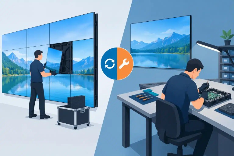
Component-level repair is often practical when a module has a limited number of failed LEDs, a damaged driver IC, broken solder joints, or localized PCB damage and a compatible replacement module is costly, unavailable, or operationally inconvenient. It can help preserve matched inventory and avoid replacing an entire panel for a repairable fault.
Replacement may be the better decision when the PCB is extensively damaged, corrosion is widespread, the module has repeated failures across multiple circuits, or the correct optical and electrical match cannot be maintained. The goal is not to repair every module at any cost. It is to make a technically sound decision that protects display performance and avoids repeated downtime.
Do not treat an intermittent pixel as fixed because it returns during a quick test. A repair should be verified at operating brightness, with relevant patterns, after sufficient run time, and with the module returned to its intended cabinet environment when possible. A pixel that comes back on is a useful clue. A pixel that stays stable through documented testing is the result the operation can depend on.

Jose de Jesus Martinez (Chuy) is the CEO of 725co. LED Repair Professionals, a trusted name in high-quality LED module repair and video wall services. With over 12 years of experience and certification as an electronic engineer, Chuy has built a reputation for excellence, partnering with industry leaders. Under his leadership, 725co is known for precision repairs, transparent service, and a commitment to protecting the long-term value of LED investments.