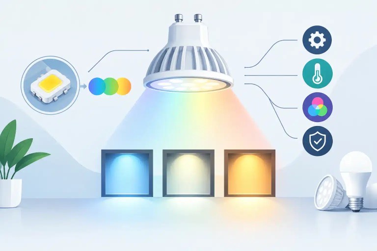
A wall can pass a basic power-on test and still fail the client-facing test: a warm vertical strip in a white background, a greenish cabinet in a gray field, or one replacement module that becomes obvious during camera shots. Understanding why LED colors shift is not about chasing one setting. In professional displays, color inconsistency can originate in the LEDs, the module electronics, calibration data, signal path, environment, or an earlier repair.
The visible symptom is often simple. The root cause rarely is. That is why a useful diagnosis starts by determining whether the shift follows a module, a cabinet position, a data port, a receiving card, or the source signal. Replacing parts before making that distinction can add cost while leaving the real fault in place.
Why LED Colors Shift Over Time
An LED pixel creates white by combining red, green, and blue emitters at controlled output levels. When the relative output of those emitters changes, the perceived white point changes with it. A display may look slightly pink, cyan, yellow, or green even when every pixel is technically illuminated.
Normal aging is one reason. Red, green, and blue LEDs do not age at identical rates, and their output changes based on operating hours, drive current, thermal conditions, and the content the display has shown. A wall that has spent years running bright static graphics, for example, may age differently than a wall used primarily for short-duration live events. Extended high-brightness operation can contribute to that effect.
This does not mean every aged panel is defective. Gradual color drift across an entire matched wall may be manageable through calibration or a revised color target. A distinct module or cabinet that is visibly different is a separate concern. That pattern points more often to a module mismatch, failed components, lost correction data, or a signal and control issue.
LED Binning and Replacement Module Mismatch
Even new LEDs vary slightly in brightness and wavelength. Manufacturers sort or “bin” LEDs to keep those variations within defined ranges. Professional modules are built and calibrated around those characteristics. When a module from another production batch is inserted into an existing wall, it may be electrically compatible but visually different.
That difference becomes especially apparent in low-gray images, white backgrounds, skin tones, and camera environments. A replacement module can match at full brightness yet stand out at 10 percent brightness because its grayscale behavior and correction data do not match the rest of the display.
The practical question is not simply whether the replacement module powers up. It is whether its LED type, scan configuration, driver IC behavior, firmware compatibility, brightness range, and calibration approach are appropriate for that wall. A close-looking substitute can create a noticeable visual exception in premium rental inventory or a fixed installation.
When Color Shift Is an Electronics Fault
A color issue that appears suddenly deserves more scrutiny than a gradual shift across years of operation. On a module, each color channel depends on driver ICs, current paths, decoupling components, data routing, and soldered connections. Damage to any of these areas can alter the output of one color or a group of pixels.
A weak blue channel may leave the module looking warm or yellow. Excess green output can create a green cast across a section. Intermittent solder joints can cause the issue to appear only after the display warms up, after transport, or when the cabinet flexes during installation. Water exposure, corrosion, physical impact, and previous improper rework can all produce faults that look like a calibration problem at first glance.
Driver IC failures are particularly easy to misread. A partially failed IC may not create a clean block of dead pixels. It can cause reduced current, unstable grayscale, or a color error across a repeating pixel pattern. Replacing LEDs alone will not correct that type of fault. The module requires component-level diagnostics to identify whether the failure is in the emitters, the IC, the PCB trace, or supporting circuitry.
Heat Changes the Diagnosis
Temperature affects LED output and electronic performance. If a color difference grows after the wall has been running for 20 minutes, thermal behavior becomes useful diagnostic evidence. Poor ventilation, blocked cabinet fans, excessive ambient heat, failing power supplies, and localized PCB damage can all contribute.
The opposite can occur in cold environments, where a marginal connection or component behaves differently until the display reaches operating temperature. For rental and live-event teams, this matters because a wall tested in the warehouse may not behave the same way under show load, in direct sun, or in a tightly built scenic structure.
A proper evaluation should include cold-start and warmed-up observation when appropriate, not just a quick visual inspection at the bench.
Color Shift Can Start Upstream of the Module
Not every color problem is a module repair issue. If the shifted area moves when modules are swapped, the fault may be tied to cabinet wiring, a HUB board, receiving card output, or data cable path. If the entire wall looks wrong, start with the processor, source, output mapping, color-space settings, and display configuration.
Incorrect RGB range, color temperature settings, gamma settings, or a processor profile can make a properly functioning wall look inaccurate. A source set to limited range while the processor expects full range may affect contrast and grayscale in ways that operators interpret as a panel issue. Improper cabinet mapping can also produce unexpected visual behavior, although it typically presents as a more obvious data or image problem.
Calibration data is another important factor. Many professional LED systems use module-level or cabinet-level correction coefficients to compensate for variation in LEDs and electronics. If that data is missing, overwritten, loaded to the wrong location, or incompatible with the receiving-card configuration, a module can display with a noticeable color or brightness difference despite having no damaged LEDs.
This is where documentation matters. Before a repair team changes configuration files or performs a factory reset, they should preserve the existing settings and identify the correct calibration data. An indiscriminate reset may turn one manageable issue into a larger wall-matching problem.
A Disciplined Way to Isolate the Cause
A practical path is controlled testing, not assumption. Start with known test patterns: full red, green, blue, white, black, multiple gray levels, and a moving image. White alone is useful, but it does not reveal which channel is drifting or whether the problem changes at low brightness.
Then isolate the physical location. Swap the suspect module with a known-good module when the system allows it. If the color shift moves with the module, focus on the module. If it stays in the same cabinet position, investigate the signal chain, power, HUB board, or receiving card. When the issue tracks a processor output, test the cable and output path before opening panels.
For module-level faults, inspection under magnification is often necessary. Technicians should look for damaged LEDs, cracked solder joints, lifted pads, corrosion, overheated ICs, damaged traces, and evidence of prior rework. Electrical measurements and controlled test fixtures help confirm whether the observed color error is caused by LED output, drive current, or data integrity.
This process also helps prevent a common mistake: treating all off-color modules as candidates for LED replacement. In some cases, calibration resolves the mismatch. In others, a quality-focused repair may require an IC replacement, PCB trace repair, or precision replacement of matched LEDs followed by validation.
Repair, Recalibration, or Replacement?
The right decision depends on the failure mode and the role of the display. A single module with a localized electronic fault may be a strong candidate for component-level repair. That can preserve matched inventory and avoid the delays or cost of sourcing an entire new module. A module with extensive water damage, severe PCB delamination, or obsolete LEDs that cannot be visually matched may be better replaced.
Recalibration is appropriate when the hardware is healthy but correction data or wall matching needs attention. It is less effective when a driver IC is degrading, LEDs have physical damage, or the module has unstable output. Calibration may reduce the visibility of a fault in some conditions, but it cannot restore a damaged current path.
For high-visibility applications, acceptance should be based on more than whether the image returns. The repaired module should be checked for color consistency, grayscale response, pixel stability, scan behavior, and operation after appropriate warm-up or extended testing when the failure type warrants it. Documented QC gives operations teams a record of what was found, what was repaired, and how the module performed during final testing.
725Co. approaches color faults this way because professional operators need more than a module that lights up on the bench. They need a well-supported repair decision that helps protect rental inventory, installation quality, and the next deployment.
When a color shift appears, capture the conditions before anyone starts swapping parts: the content on screen, brightness level, run time, cabinet location, processor settings, and whether the issue moves with a module. Those details turn a frustrating visual defect into evidence, and good evidence provides a stronger basis for a repair that can be properly tested and verified before returning to service.

Jose de Jesus Martinez (Chuy) is the CEO of 725co. LED Repair Professionals, a trusted name in high-quality LED module repair and video wall services. With over 12 years of experience and certification as an electronic engineer, Chuy has built a reputation for excellence, partnering with industry leaders. Under his leadership, 725co is known for precision repairs, transparent service, and a commitment to protecting the long-term value of LED investments.