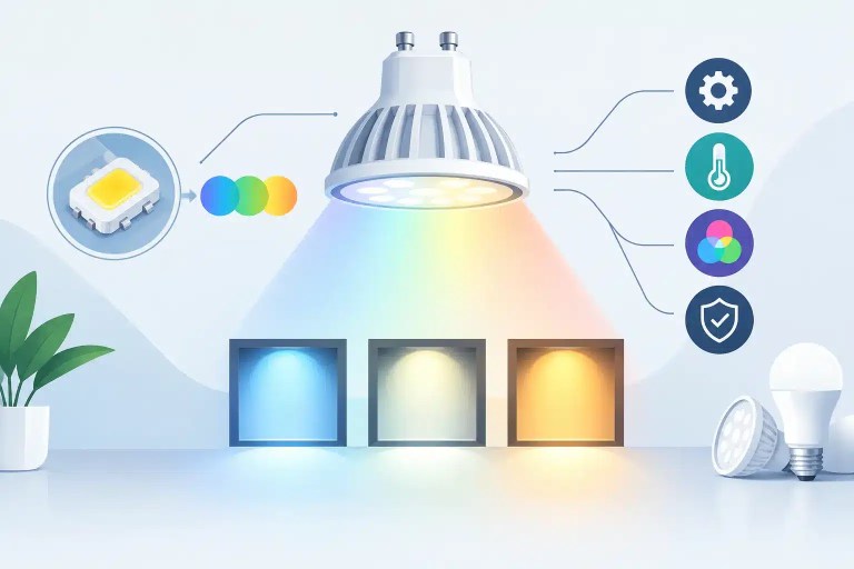
A color mismatch is rarely just a cosmetic issue when an LED wall is on camera, in a casino, or above a live audience. A practical way to correct LED color mismatch is to determine whether the problem follows a specific module, stays in a physical screen location, or appears across an entire signal path. Those three outcomes point to very different repair paths.
A panel that looks slightly green, warm, dim, or desaturated can be caused by aging LEDs, an incorrect receiving-card configuration, a failed driver IC, poor module data, a replacement module from a different production batch, or calibration that no longer reflects the wall’s actual condition. Replacing the first suspect module may hide the symptom temporarily, but it does not necessarily resolve the root cause.
For AV rental companies, integrators, production teams, and venue operators, the goal is not simply to make a wall look acceptable in the shop. It is to return it to stable, consistent performance under the conditions where it will actually be used.
Why LED Color Mismatch Happens
Professional LED displays create white and full-color images by balancing red, green, and blue LEDs at controlled brightness levels. If one color channel changes in output, the eye notices it quickly, especially on white, gray, skin-tone, and low-saturation content. A minor shift that is hard to see on a moving graphic can become obvious on a corporate presentation slide or a camera shot.
The source may be localized to one module or spread across a cabinet. A module with a blue or yellow cast can have different LED binning than adjacent modules, uneven LED aging, or a damaged color channel. A vertical or horizontal color band may instead indicate a data issue, receiving-card configuration problem, ribbon cable fault, or driver IC failure affecting a repeated pixel area.
Color mismatch also appears after otherwise reasonable field repairs. A replacement module may match the physical pitch, scan rate, and connector layout while still using different LEDs, masks, driver IC behavior, or factory calibration data. It powers up and displays video, but it does not visually belong in the wall.
Aging Is Not Uniform
LEDs lose output over time, but they do not all age at the same rate. Usage patterns matter. A wall that has spent years displaying bright white digital signage will age differently from a rental product used intermittently for dark concert content. Heat, operating brightness, airflow, power stability, and prior component failures all influence the rate of change.
This is why installing a brand-new module into an older wall can create a more obvious mismatch than the original defect. The new module may be technically correct yet visibly brighter and cooler than the surrounding inventory. In that situation, calibration may be part of the answer, but only after confirming that the existing modules are electrically healthy.
Calibration Data Can Be Wrong, Missing, or Incomplete
Many professional LED products depend on module-level or cabinet-level calibration coefficients to normalize brightness and color. If that data is lost, overwritten, applied to the wrong cabinet, or bypassed during a controller change, the resulting image may have obvious color variation even when the hardware is intact.
Calibration is not a universal cure. It cannot reliably compensate for a failed driver output, a degraded LED channel, or a module built with materially different components. It is a controlled adjustment tool, not a substitute for diagnosis.
How to Correct LED Color Mismatch Without Guesswork
Start with a known test environment. Display full-field red, green, blue, white, and neutral gray patterns at a consistent brightness. Then inspect the wall both close up and from normal viewing distance. The color that is missing or excessive often provides the first useful clue.
A problem that only appears on gray or white often involves subtle channel balance, calibration, or aging. A module that drops red completely, shows a sharply defined cyan area, or changes color with image content is more likely to have a hardware or data-path issue. Photographing the wall under controlled test patterns also creates a record that can be compared after repair.
Determine Whether the Fault Follows the Module
Move the suspect module to a known-good position, where practical and safe. If the color issue moves with it, focus on the module. If it remains in the original cabinet location, inspect the cabinet-side signal path, power distribution, receiving card, hub board, cables, and configuration.
This single isolation step helps prevent a common and expensive mistake: replacing good modules because the actual fault is upstream. In rental inventory, it also helps separate a module defect from a cabinet that may continue damaging or misconfiguring replacement modules.
When the issue follows the module, compare it to an adjacent known-good unit with the same part number and revision. Check the LED package type, driver IC, scan configuration, and stored calibration data. Physical compatibility alone is not enough. A visually matched repair requires electrical and optical compatibility.
Verify the Signal and Control Layer
If the mismatch stays in the cabinet position or appears across multiple modules in a pattern, investigate the control system before touching LEDs. Confirm that receiving-card firmware, module configuration files, mapping, bit depth, and color settings are correct for the product. Check whether a processor or controller change preceded the issue.
A configuration error can create conditions that look like module failure: incorrect color order, improper grayscale behavior, uneven brightness, or repeated banding. Damaged ribbon cables, contaminated connectors, and failing hub boards can also corrupt data to a module row or column.
Power should be checked under load, not only with the wall idle. A weak supply, poor connection, or voltage drop can alter drive behavior and cause brightness or color instability. If the color shifts as content brightness rises, thermal or power-related behavior deserves close attention.
Inspect the Module at Component Level
When testing confirms a module-level fault, the repair process should move beyond visual inspection. Professional diagnosis may include checking for damaged LEDs, failed or weakened driver IC outputs, cracked solder joints, lifted pads, trace damage, missing passive components, and prior rework that compromised the PCB.
A single failed driver IC can affect a defined group of pixels or one color channel. A bad solder joint may appear stable on the bench but develop problems when the module heats up during a show. Poor previous repair work can introduce a different LED bin, overheated pads, solder bridges, or intermittent failures that do not show up until the module is reinstalled.
Microscope-level inspection and precision rework matter because LED modules are dense assemblies. The correct repair is not simply replacing an LED that looks dark. It is confirming why that LED or channel failed, restoring the damaged component or connection, and testing the module through appropriate operating conditions.
When Calibration Is the Right Fix
Calibration is appropriate when the modules are functional, compatible, and consistently driven, but their brightness or color balance has drifted. It may be used after a matched module repair, during an inventory refresh, or when an older wall needs more uniform presentation quality.
The trade-off is that calibration works within limits. Bringing a bright replacement module down to match an older wall can improve uniformity, but it may reduce the wall’s overall usable brightness. Raising older, degraded modules to chase a new module is usually not practical and can place additional stress on aging components.
For high-visibility installations and camera-facing applications, document the baseline: test patterns, processor settings, module revisions, brightness level, and observed results. That record makes future troubleshooting faster and helps identify whether a new mismatch is aging-related, repair-related, or caused by a change in the signal chain.
When Replacement Is More Practical Than Repair
Component-level repair is often the practical choice when replacement modules are unavailable, backordered, discontinued, or likely to create a visible batch mismatch. It can also preserve the consistency of a rental fleet by returning original modules to service rather than introducing unverified substitutes.
Replacement may be the better decision when a module has extensive PCB damage, severe heat exposure, multiple prior repair attempts, or widespread LED degradation. The right choice depends on the wall’s age, available spares, expected service life, visual requirements, and the cost of downtime. An experienced technical repair partner should be willing to identify when further rework is no longer the responsible option.
725Co. approaches color defects by isolating the source first, then performing component-level repair or recommending a practical replacement path based on the condition of the equipment. Final testing and documented QC are especially valuable when the module is heading back into rental inventory or a high-visibility installation.
A clean, repeatable test record is valuable protection against the next color issue. When a wall returns from repair with verified patterns, confirmed configuration, and documented results, your team has more than a panel that looks better — it has a useful reference for keeping the full display consistent.

Jose de Jesus Martinez (Chuy) is the CEO of 725co. LED Repair Professionals, a trusted name in high-quality LED module repair and video wall services. With over 12 years of experience and certification as an electronic engineer, Chuy has built a reputation for excellence, partnering with industry leaders. Under his leadership, 725co is known for precision repairs, transparent service, and a commitment to protecting the long-term value of LED investments.