A damaged LED module does not automatically need to become a replacement order. PCB reconstruction for LED panels can restore a board that has lifted pads, torn traces, damaged connectors, failed components, or evidence of poor prior repair work. For AV rental teams, integrators, venues, and production companies, the real question is not simply whether a panel powers up. It is whether the repair has been properly evaluated, tested under appropriate operating conditions, and returned to a reliable working condition.
That distinction matters when a failed module is holding up a rental deployment, affecting a high-visibility install, or creating visible defects in a wall that must perform before doors open. A board-level repair can be a practical alternative to replacement, but only after the underlying failure is properly identified.
What PCB Reconstruction Actually Means
PCB reconstruction is not the same as swapping an LED module, replacing a loose cable, or touching up a solder joint that is easy to reach. It is a controlled board-level repair process used when the printed circuit board itself has been physically or electrically compromised.
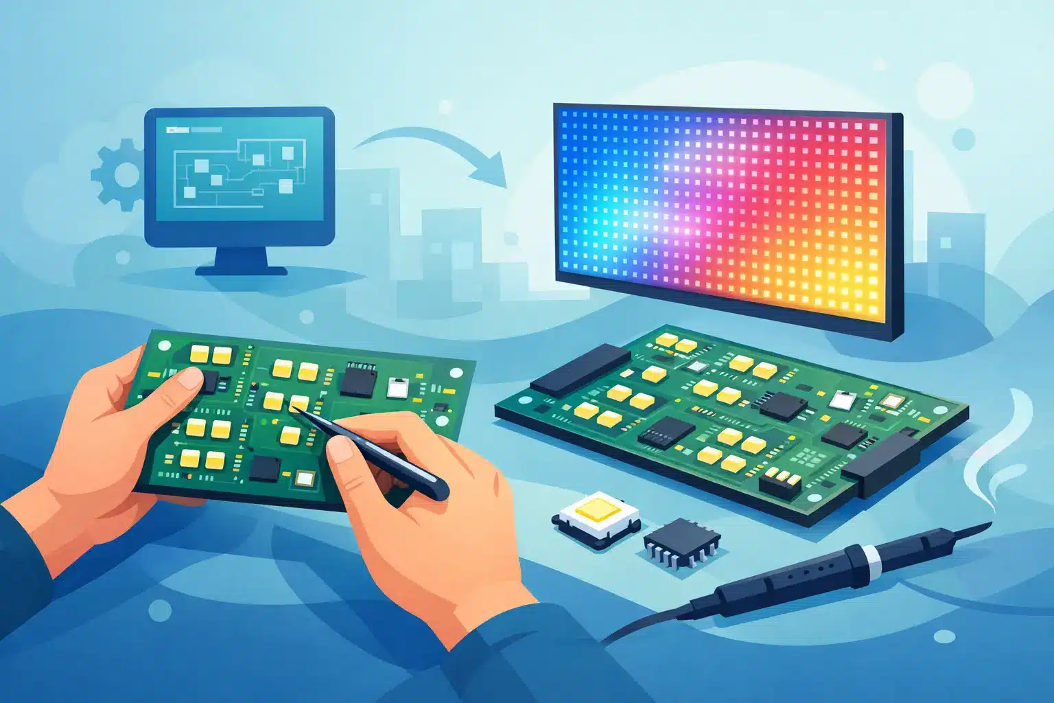
On an LED panel module, that may include rebuilding a lifted copper pad beneath a driver IC, repairing a broken trace, restoring a damaged via connection, reconstructing a connector landing area, or correcting damage caused by moisture, impact, overheating, or an unsuccessful prior repair. The goal is to restore the intended electrical path without creating an obvious weak point that may contribute to failure during transport, thermal cycling, or extended runtime.
LED modules are densely packed assemblies. A repair around a driver IC or LED package may involve extremely small pads, fine-pitch soldering, and signal paths that cannot be guessed at. A repair that looks clean to the naked eye can still create intermittent data loss, incorrect color output, scan-line issues, or recurring pixel failures once the module is placed back in service.
Start With Diagnosis, Not the Visible Damage
A torn pad or burned area on a board may be obvious, but it is not always the reason the module failed. A row of dark pixels, for example, can originate from a damaged trace, a failed driver IC, a power distribution issue, a receiving-card configuration problem, or a problem upstream from the module itself.
This is where rushed repair decisions can create expensive repeat failures. Replacing an IC without checking the connected circuits can damage the new component. Rebuilding a trace without verifying whether a short caused the damage can send the same fault back into the repaired area. Installing a replacement module without checking calibration and batch compatibility can solve one problem while creating a visible color or brightness mismatch across the wall.
A proper assessment considers the module’s power rails, data paths, scan behavior, IC outputs, physical board condition, and the symptoms seen in the complete panel. Technicians also need to consider the display environment. A module used in a touring rental wall faces vibration, handling, frequent assembly, and fast turnaround pressure. A fixed casino or corporate installation may be exposed to long daily runtimes, heat accumulation, or environmental contamination. The repair decision should reflect those conditions.
When PCB Reconstruction for LED Panels Is a Practical Option
Reconstruction is most useful when the failure is localized and the module remains otherwise viable. This often applies to boards with connector damage, lifted pads from a previous IC replacement, broken data or power traces, isolated corrosion damage, or a limited area affected by impact.
It can also make sense when an exact replacement module is unavailable, has an unacceptable lead time, or could introduce compatibility issues. Professional LED products change over time. Even when a replacement looks similar, differences in LED binning, driver configuration, scan rate, mask design, brightness, or calibration behavior can be noticeable on camera and to the eye.
For rental inventory, preserving a matched pool of modules can be more valuable than buying a small number of newer substitutes that do not blend correctly with the existing wall. For installed systems, reconstruction may help maintain display consistency while a longer-term replacement plan is evaluated.
That said, not every board should be rebuilt. A severely delaminated board, extensive liquid damage, broad thermal damage, repeated failures across multiple circuits, or damage involving internal layers may make replacement the more appropriate decision. The right answer depends on the board condition, product availability, repair history, operational deadline, and the role that module plays in the display.
The Technical Risks of Shortcut Repairs
A common failure pattern begins with a module that was repaired quickly under pressure. An IC was removed with excessive heat, pads were lifted, and jumper wires were added without proper strain relief or insulation. The module may work on the bench, then develop problems after a few hours in a wall or after the next load-in.
The issue is not that jumpers or pad repairs are inherently wrong. In some cases, they are the correct method. The issue is whether the repair restores electrical integrity and mechanical stability at the level the application requires.
Fine-pitch IC work requires controlled heat, appropriate soldering methods, accurate alignment, and inspection under magnification. Reconstructed traces need correct routing and secure bonding. Damaged pads must be rebuilt with enough mechanical support to withstand the repair process and future service. Contamination, solder bridges, and marginal joints should be identified before the board is returned to a panel.
A professional repair process also recognizes that a module can pass a basic power-on test and still require additional evaluation before returning to service. Intermittent failures are especially disruptive in live production because they may appear only after warm-up, vibration, handling, or sustained video content.
A Better Repair Process for Professional LED Inventory
For a repair to be operationally useful, it needs to be traceable. The incoming condition should be documented, including visible damage and reported symptoms. From there, the board should be diagnosed at component level rather than treated as a generic bad module.
The repair itself may involve replacing LEDs, driver ICs, passive components, connectors, or reconstructing damaged PCB features. The exact work should follow the failure, not a preset repair script. If a failed IC is only a symptom of a power or data problem, that problem needs attention before the module is considered complete.
After repair, quality control should include inspection for workmanship, electrical verification, functional testing, and visual testing in an appropriate panel or wall environment. Depending on the failure type, extended runtime testing may be useful for identifying thermal or intermittent issues. Documentation gives technical managers and purchasing teams a clear record of what was found, what was repaired, and how the module was tested.
This process matters because an LED wall is a system. A repaired module must communicate correctly with adjacent modules, display stable color and data behavior, and operate within the expectations of the controller, receiving card, power system, and cabinet design.
Replacement Cost Is Only Part of the Decision
The cheapest path on paper is not always the lowest-risk path in the field. A replacement module may carry shipping delays, minimum-order requirements, calibration concerns, or uncertainty about exact compatibility. On the other hand, reconstruction may not be appropriate when damage is too extensive or when the repair risk exceeds the value of the module.
The practical evaluation should include the cost of downtime, the value of keeping rental inventory matched, the availability of spares, and the consequences of a recurring failure during a show or installation. For high-visibility or time-sensitive deployments, maintaining tested spare modules remains a sound operational practice even when board-level repair is available.
With more than a decade of technical service supporting professional AV organizations, 725Co. approaches that decision as a repair and reliability question, not a reason to force every damaged board back into service. Sometimes reconstruction helps protect a valuable asset. Sometimes the more responsible recommendation is replacement. Both outcomes begin with accurate diagnosis.
Protecting Repaired Modules After They Return to Service
A reconstructed PCB should not disappear into inventory without a record. Labeling repaired modules, retaining QC results, and tracking repeat issues by product line can reveal patterns that are otherwise missed. If several modules show the same connector damage, thermal area, or driver failure, the issue may involve handling practices, cabinet alignment, power distribution, or a recurring system-level condition.
For rental operations, transport protection and consistent module handling can prevent many of the impacts that lead to broken corners, cracked boards, and damaged connectors. For fixed installations, periodic inspection of power, ventilation, and cabinet conditions can reduce avoidable heat and contamination damage.
When an LED module fails, the fastest-looking solution is often the one that creates the next problem. A careful board-level evaluation gives your team a better basis for deciding whether to reconstruct, replace, or investigate the wider system before the next deployment puts the display under pressure.

Jose de Jesus Martinez (Chuy) is the CEO of 725co. LED Repair Professionals, a trusted name in high-quality LED module repair and video wall services. With over 12 years of experience and certification as an electronic engineer, Chuy has built a reputation for excellence, partnering with industry leaders. Under his leadership, 725co is known for precision repairs, transparent service, and a commitment to protecting the long-term value of LED investments.