A module with a dark section, intermittent row, wrong color, or physical damage is not automatically a replacement module. The difference between repairable versus nonrepairable modules often comes down to the actual failure point, the condition of the PCB, and whether a proper diagnosis has separated the symptom from its cause. For rental houses, production teams, integrators, and venues, that distinction directly affects uptime, spare inventory, and replacement spending.
A visible display issue may originate in an LED, driver IC, connector, trace, power path, receiving card, cabinet harness, processor setting, or calibration data. Replacing a module before that chain is evaluated can solve the immediate symptom, but it can also leave the root problem in place. This is why a practical repair decision begins with diagnosis, not a visual judgment alone.
What Makes an LED Module Repairable?
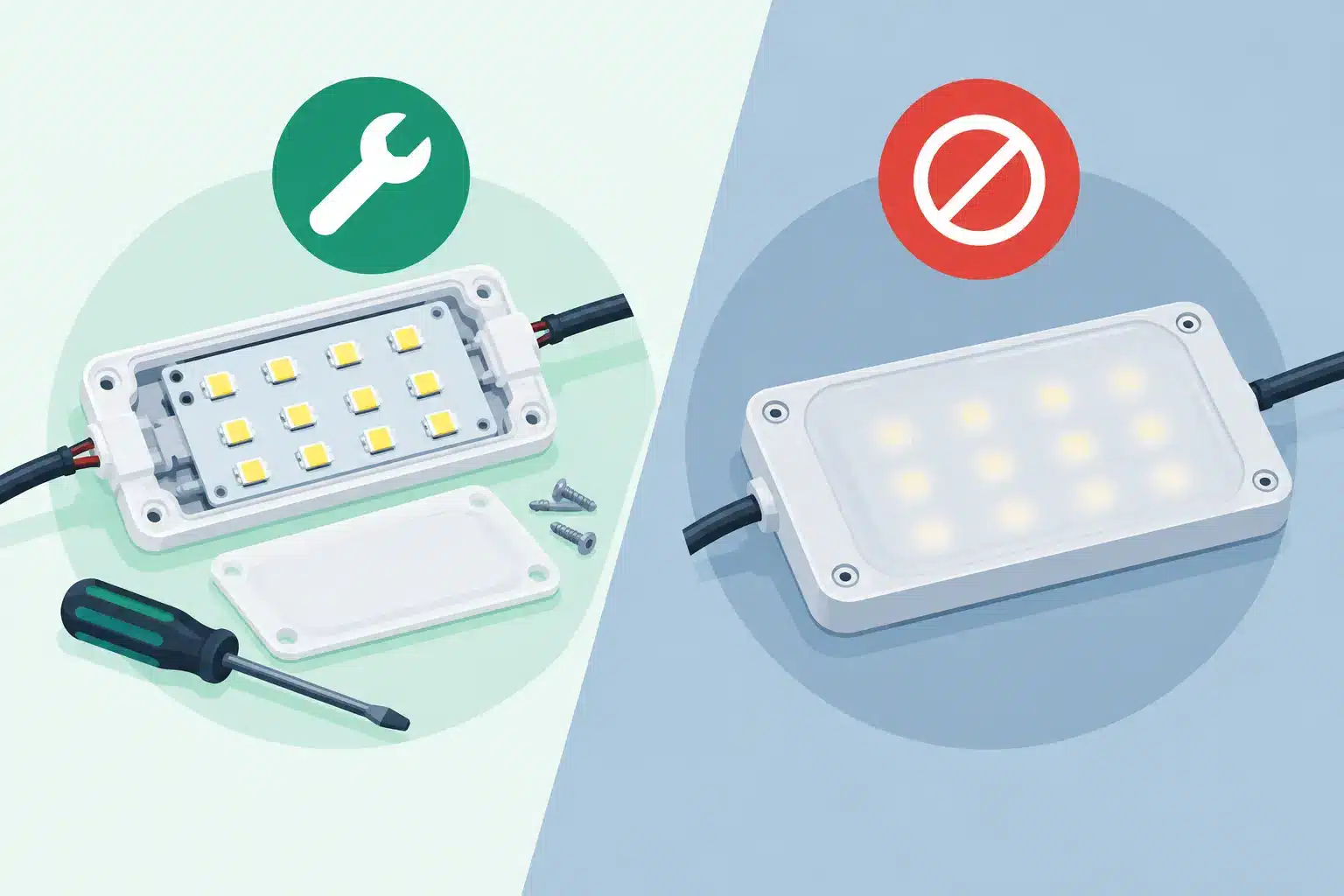
A repairable module has a fault that can be corrected at the component or board level without compromising the module’s long-term performance. Common examples include failed LEDs, damaged driver ICs, cold or fractured solder joints, defective passive components, connector damage, and isolated PCB trace failures.
Pixel-level faults are often the most recognizable. A single dead, dim, stuck, or color-shifted pixel may be caused by the LED package itself, but it may also point to a driver channel, solder connection, or signal issue. A technician needs to identify which condition exists before replacing a component. Installing a new LED on a module with a failing driver IC may produce a short-lived result or no result at all.
Driver IC replacement is another common component-level repair. When an IC fails, the problem may appear as a dead column, a row with incorrect color behavior, flickering, ghosting, or inconsistent brightness. The repair requires more than removing and replacing the package. Pad condition, solder quality, surrounding circuitry, module scan behavior, and final image performance all need to be checked under test.
Physical damage does not always make a module nonrepairable. A damaged corner, lifted component, broken connector, or localized impact area may be recoverable if the PCB layers remain structurally sound and the affected circuitry can be restored. The deciding factor is whether the repair can return the module to reliable service, not simply whether a damaged part can be made to light up.
Repairable Versus Nonrepairable Modules: The Real Factors
The repairability decision is rarely based on one fault alone. It depends on the module’s electrical condition, physical condition, availability of compatible components, and the operating standard required by the application.
A module may be technically repairable but not operationally appropriate to repair. For example, a heavily worn module with multiple prior repairs, recurring intermittent faults, severe environmental exposure, and poor brightness consistency may not be a good candidate for a high-visibility wall. It might still be useful as a controlled spare or for a less demanding application, but that decision should be deliberate.
Conversely, a module that looks severely damaged may be worth repairing if it is from an older or discontinued product line where replacement stock is limited, expensive, or mismatched. In those cases, a board-level repair can help preserve usable inventory while the organization plans a longer-term replacement strategy.
PCB Damage and Layer Integrity
PCB condition is one of the clearest dividing lines. Surface-level damage, broken traces, damaged pads, or localized corrosion can often be repaired when the affected area is accessible and the board structure is stable. Multilayer PCB damage is more complicated. Internal layer failures, extensive delamination, carbonized material, or widespread corrosion can create faults that are difficult to isolate and may return under thermal or mechanical stress.
A repair should not be judged only by whether it powers on at the bench. Professional LED modules need stable behavior through testing, signal verification, color evaluation, and inspection. If a board cannot hold that standard, replacement is usually the more responsible decision.
Repeated or Systemic Failures
One failed module in an otherwise stable wall suggests a localized problem. Several modules with the same symptom may indicate a larger issue involving power distribution, data routing, environmental conditions, receiving card configuration, processor output, or handling practices.
In that situation, repairing every affected module without investigating the system can create a cycle of repeat failures. A row of damaged driver ICs, for example, may be related to a voltage problem or a signal condition that needs to be corrected before repaired inventory returns to service. The module repair and the system diagnosis should support each other.
Component Availability and Compatibility
Professional LED modules are not interchangeable simply because pixel pitch or physical dimensions look similar. LED package characteristics, driver IC behavior, scan configuration, mask design, brightness, color performance, and mechanical fit all influence whether a replacement component or module will work properly.
Component availability also matters. A repair may be feasible when the correct LED type, IC, connector, or passive component can be sourced and verified. If compatible components are no longer available, the risk of color mismatch, brightness variation, or unstable performance can outweigh the benefit of attempting the repair.
Why Visual Inspection Is Not Enough
A dark module can be a module problem, but it can also be a cabinet, cable, hub board, receiving card, or processor issue. The fastest reliable way to separate those possibilities is controlled testing.
A useful diagnostic process typically includes confirming the symptom, checking power and signal paths, comparing the module against known-good positions or components, inspecting the board under magnification, and testing the repaired module before release. Depending on the fault, that process may also involve examining configuration, mapping, refresh behavior, calibration, and the upstream control chain.
This level of diagnosis matters most when the symptom is intermittent. Modules that fail only after warm-up, movement, transport, or extended runtime can be particularly disruptive in rental and live-event environments. A quick power-on test may miss the condition entirely. Testing needs to reflect the way the inventory will actually be used.
When Replacement Is the Better Decision
Replacement is often appropriate when damage is widespread, PCB integrity is compromised, the module has become unreliable after repeated failures, or compatible components cannot be verified. It is also the right path when a repair would create an unacceptable cosmetic or performance mismatch in a critical viewing area.
Replacement can be complicated by discontinued product lines and batch variation. A new module may require calibration, configuration, or brightness and color matching before it blends into an existing wall. For that reason, replacement is not always a simple purchase decision either. It should be evaluated as part of the entire display system.
For organizations managing a large inventory, the best approach is usually not repair or replacement as an absolute rule. It is a controlled triage process. Repair modules with isolated, verifiable faults. Retire modules with structural or recurring reliability concerns. Reserve known-good spares for critical deployments. Track patterns that indicate a cabinet or system-level cause.
Building a Better Module Triage Process
An effective intake process prevents technicians and operations teams from treating every faulty module the same way. Start by documenting the product line, module serial or asset information, reported symptom, cabinet location, known event history, and prior repair history. A photo or video of the active fault is useful, especially when the issue is intermittent.
Next, separate modules by failure type rather than by appearance alone. Dead pixels, color defects, row or column faults, no-power conditions, physical damage, and intermittent behavior each point toward different diagnostic paths. Modules should then be tested against a known-good environment whenever possible, so upstream issues are not incorrectly assigned to the board.
The final disposition should be clear: repaired and tested, repairable pending parts, not repairable due to identified board damage, or held for further system diagnosis. That documentation helps operations teams make sound inventory decisions and gives technical staff a history to reference when a pattern develops.
With 14 years of technical service supporting professional AV organizations, including teams at Freeman, 4Wall, and PRG, 725Co. approaches module evaluation as an accountability process. Component-level work, microscope inspection, professional soldering, and documented QC are intended to establish whether a module is truly ready to return to service, not merely whether it can display an image for a few minutes.
The next time a module fails, preserve the failure information before swapping it out. The symptoms, cabinet position, and operating conditions may be the evidence that turns a costly replacement decision into a repairable, documented solution.

Jose de Jesus Martinez (Chuy) is the CEO of 725co. LED Repair Professionals, a trusted name in high-quality LED module repair and video wall services. With over 12 years of experience and certification as an electronic engineer, Chuy has built a reputation for excellence, partnering with industry leaders. Under his leadership, 725co is known for precision repairs, transparent service, and a commitment to protecting the long-term value of LED investments.