
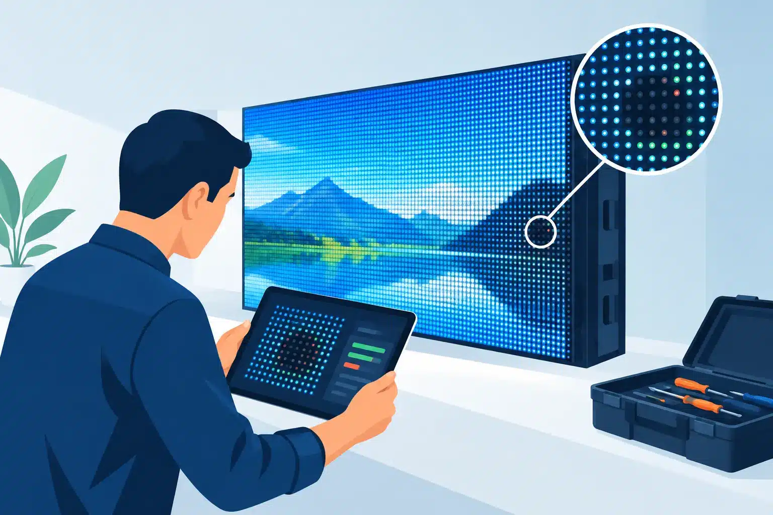
A single dark section on an LED wall can look like a failed module. A red-tinted column may appear to be a calibration problem. An intermittent cabinet can seem like a receiving card issue until it returns from a rushed repair with the same fault still present. This is where LED diagnostics matter: the visible symptom is only the starting point, not the diagnosis.
For professional AV teams, a wrong diagnosis costs more than a repair attempt. It can take inventory out of rotation, create last-minute show risk, consume spare modules, and lead to replacement decisions that may not be necessary. A disciplined diagnostic process identifies where the failure actually lives, confirms whether it is repeatable, and provides a repair path that can be tested and documented.
What Professional LED Diagnostics Actually Involve
Professional LED diagnostics are a structured evaluation of the full display signal and power path. The objective is not simply to identify a bad panel. It is to determine whether the fault originates in the LED module, driver IC, PCB trace, connector, hub board, receiving card, power supply, data cable, processor, configuration, or an interaction between those components.
That distinction matters because LED walls are systems, not isolated cabinets. A module may display a fault because it is receiving incorrect data. A cabinet may flicker because of a marginal power connection upstream. A processor configuration issue can resemble a hardware problem, especially after a system change, firmware update, or deployment using equipment from different inventory batches.
A useful diagnostic process begins by documenting the reported symptom and operating conditions. Is the failure constant, heat-related, movement-related, or intermittent? Does it appear on one input, one output, one cabinet position, or across the wall? Has the module been swapped, and did the fault move with it? These details help separate a true component failure from a signal-path or environmental issue.
Start With the Symptom, Then Isolate the Fault
Visual inspection is valuable, but it cannot stand alone. Physical damage, lifted pads, damaged connectors, corrosion, heat discoloration, and poor prior solder work can provide immediate clues. Yet a clean-looking module can still have failed driver ICs, damaged data paths, cold solder joints, or PCB-level defects that only appear under load.
Isolation is the critical next step. Technicians may compare a suspect module against a known-good module, test it in a controlled cabinet position, inspect power and data continuity, and verify behavior with appropriate test patterns. Solid colors, grayscale patterns, scan tests, and moving content can expose faults that are not visible on a static image.
For example, one dead pixel is not always one failed LED. Depending on the module design and pixel behavior, the source may be the LED package, its solder connection, a damaged trace, or a driver IC channel. Replacing a pixel without confirming the underlying cause can produce a temporary result or introduce a new issue.
Common Faults and What They Can Mean
A symptom is evidence, not a verdict. The same visible behavior can have different causes depending on the display architecture, pixel pitch, scan rate, module design, and system configuration.
Dead, dim, or incorrect-color pixels often point toward LED package failure, solder-joint damage, driver-channel failure, or local PCB damage. If several pixels fail in a repeatable pattern, the fault may follow a driver IC output group rather than individual LEDs. That pattern is a meaningful diagnostic clue and can prevent unnecessary pixel replacement.
Horizontal or vertical lines may be related to data routing, driver ICs, row or column circuits, ribbon connections, or hub board communication. If the line remains with the module after it is moved, module-level diagnosis becomes more likely. If it remains in the cabinet location, the investigation should extend to cabinet wiring, receiving hardware, and power distribution.
Flickering, random flashing, or intermittent dropout requires careful testing because the issue may only appear after warm-up or under full brightness. Marginal power supplies, loose connectors, damaged cable assemblies, unstable signal paths, and compromised solder joints can all create similar symptoms. Testing only at low brightness on a bench may miss a problem that appears during a high-output live event.
Color inconsistency can also be more complicated than a bad module. Calibration and brightness settings should be verified before hardware repair begins. However, if one area cannot reproduce expected color values during testing, the cause may be an LED, driver circuit, or module-specific electrical issue. The right sequence prevents a configuration question from becoming an unnecessary hardware repair, or vice versa.
Why Module Swapping Is Useful, but Not a Final Answer
Swapping modules is one of the fastest field tests available to an AV technician. If the problem moves with the module, that is strong evidence that the module needs attention. If the problem stays in the same physical location, the cabinet, hub board, receiving card, cable path, or power path deserves closer evaluation.
But module swapping has limits. It can disturb connectors, temporarily change a marginal contact condition, or mask an intermittent failure. It also does not explain why the module failed. For rental operations and high-value display inventory, understanding the cause can be as important as restoring the image. Repeated driver IC failures, recurring pixel defects, or damage concentrated around specific connector areas may reveal handling, power, or environmental issues that need to be addressed beyond one repair.
A documented diagnostic result gives operations teams a better basis for deciding what to repair, what to monitor, and what to remove from service. It also helps procurement and technical leadership distinguish between isolated damage and a recurring reliability pattern.
Component-Level Repair Changes the Decision
When a module has failed, replacement is sometimes the correct answer. A matching spare may be available, the module may have widespread physical damage, or the repair cost may not be justified by its condition. The practical answer depends on the display model, availability of compatible inventory, age of the product, and deployment schedule.
However, replacement is not the only answer. For professional systems, replacement modules may be delayed, discontinued, difficult to color-match, or financially impractical at scale. Component-level repair can address specific failed LEDs, driver ICs, connectors, traces, and PCB defects while preserving usable inventory.
This work requires more than basic soldering. Fine-pitch LED modules demand controlled heat, proper component handling, microscope-level inspection, and verification that the repaired area performs correctly after reassembly. A repair that looks acceptable from several feet away may still show brightness variation, color inconsistency, unstable operation, or poor solder integrity under test.
725Co. approaches these decisions as a technical service problem: identify the real fault, repair only what the evidence supports, and verify the result before the module returns to operational inventory.
Testing Must Match Real Operating Conditions
A repaired module should not be cleared simply because it powers on. Final testing should confirm pixel operation, color response, scan behavior, data stability, and performance at appropriate brightness. Where relevant, the module should be evaluated alongside compatible equipment so technicians can identify visible differences before it reaches a client’s wall.
Heat and runtime matter as well. Some faults emerge only after components reach operating temperature. Intermittent behavior may require extended observation, repeated test cycles, or controlled movement of connectors and assemblies. The exact test plan depends on the reported issue, but the standard should remain the same: test the failure mode that caused the module to leave service, not just a convenient substitute condition.
Documented quality control is especially useful for rental houses, integrators, and multi-site operators. It creates accountability around what was received, what was found, what was repaired, and what was verified. That information supports inventory decisions and gives technical teams a record to reference if a related issue appears later.
When to Escalate Beyond Field Troubleshooting
Field troubleshooting can resolve many straightforward problems, particularly loose connections, mapping errors, damaged cables, and obvious module failures. Escalation makes sense when a fault recurs after swaps, when multiple modules show similar behavior, when a prior repair did not hold, or when the cause cannot be confirmed without component-level inspection.
It is also worth escalating processor and controller concerns when a display exhibits inconsistent mapping, signal dropout, unexpected output behavior, or faults that change with inputs and configurations. A module repair will not solve a processor issue, and a processor reset will not repair a damaged data path on a module. Separating those possibilities early reduces wasted time.
For teams under event deadlines, the best diagnostic information is specific: the affected product, module position, visible symptom, duration, recent changes, prior troubleshooting, and whether the problem follows the module or cabinet. That record shortens the path from reported failure to practical repair decision.
The next time an LED wall shows a defect, resist the pressure to label it from the first symptom. A methodical diagnosis can turn a vague display problem into a defined technical issue, protect usable inventory, and help your team return equipment to service with greater confidence.

Jose de Jesus Martinez (Chuy) is the CEO of 725co. LED Repair Professionals, a trusted name in high-quality LED module repair and video wall services. With over 12 years of experience and certification as an electronic engineer, Chuy has built a reputation for excellence, partnering with industry leaders. Under his leadership, 725co is known for precision repairs, transparent service, and a commitment to protecting the long-term value of LED investments.


5 Responses