
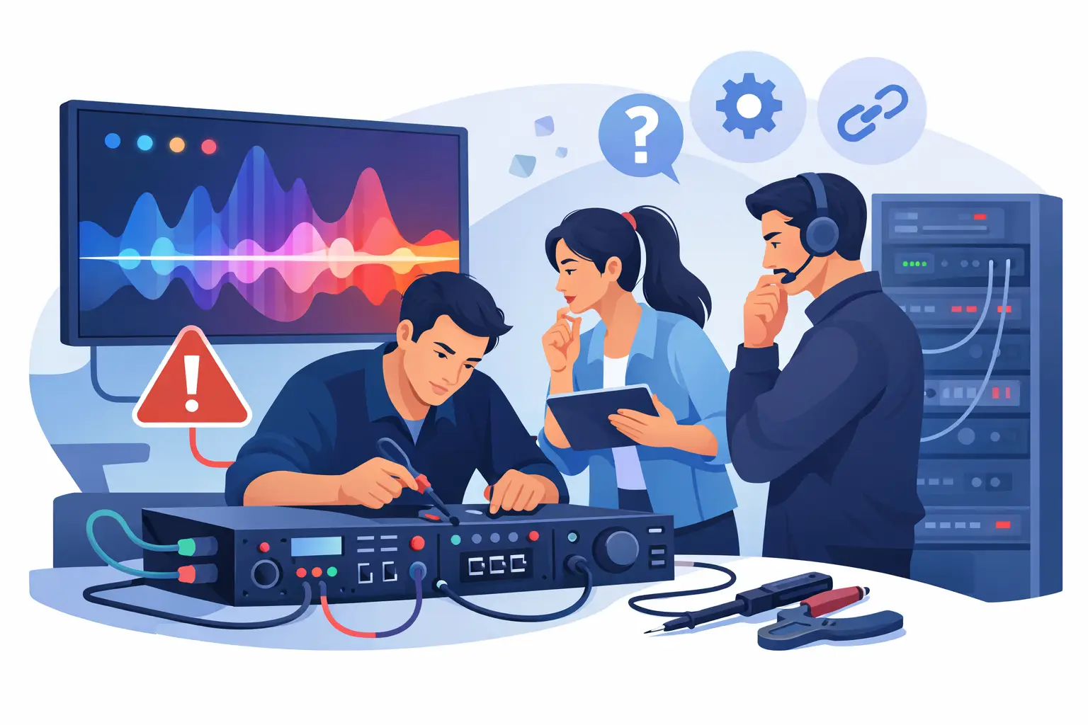
A video wall can look like it has a module failure when the actual fault is upstream: one bad Ethernet run, an incorrect receiving-card configuration, a processor output issue, or a mismatched cabinet file. Effective LED controller troubleshooting starts by separating what the wall is showing from what is actually failing. That distinction helps protect show schedules, rental inventory, and budgets.
For professional AV teams, the goal is not simply to restore an image. It is to identify the failed layer, verify the corrective action under operating conditions, and document how the system performed before the next deployment. Rebooting equipment may recover a wall temporarily, but it rarely answers why the failure occurred.
Start LED Controller Troubleshooting at the System Level
An LED display signal path has several points where a fault can be introduced: source device, switcher or matrix, processor, sending card, fiber conversion, network cable, receiving card, module hub board, and the module itself. A visible symptom at the cabinet does not automatically identify the failed component.
Before changing settings or swapping hardware, record the failure pattern. Is the issue isolated to one cabinet, one daisy-chain branch, one processor output, or every output? Does it occur at a specific resolution or refresh rate? Does it appear after warm-up, after transport, or only when a particular source is active? These details reduce unnecessary replacement and help prevent a configuration issue from being mistaken for physical damage.
A practical first pass should confirm three things: the processor is receiving a stable source signal, it is outputting the intended format, and the receiving-card chain is communicating as expected. Compare the processor status to the wall itself. If the controller reports normal output but a branch is dark or corrupted, move downstream. If the processor cannot lock to the source, do not begin replacing cabinets.
Confirm the Source Before Blaming the Processor
A black screen, intermittent image, color shift, or unstable sync may originate at the source or switching layer. Test with a known-good source and known-good input cable, using a format the processor and wall are already known to support. This is particularly useful after a show file, EDID setting, frame-sync setting, or output resolution has changed.
A processor may pass a signal at one frame rate but fail to scale or synchronize correctly at another. HDMI, SDI, DisplayPort, and fiber paths can each introduce their own failure points. A source that looks stable on a confidence monitor is not proof that it is delivering the correct format to the LED processor.
Document the input resolution, frame rate, color space, and output mapping before making changes. For installed systems, keep a verified baseline configuration available. For rental systems, include it with the prep documentation. That small discipline can help prevent an emergency technician from rebuilding a correct configuration from memory at load-in.
Read the Failure Pattern on the LED Wall
The shape of the visual fault often tells you where to test next. A full wall failure points toward source, processor, power, or primary data distribution. A clean vertical or horizontal break may indicate output mapping, a disconnected data path, or a failed receiving-card chain. Random sparkles, flashing pixels, or intermittent blocks can indicate signal integrity, a damaged cable, poor connector contact, or an unstable receiving card.
If a single cabinet is black while cabinets after it in the chain are also dark, inspect the incoming and outgoing data path at that cabinet before treating it as a module problem. If the downstream cabinets continue operating normally, the issue may be local to the cabinet: receiving card, hub board, cabinet power, internal harness, or module data distribution.
Color errors require similar discipline. An entire cabinet with a strong red, green, or blue tint may be receiving incorrect configuration data, losing one color channel at the module level, or operating with an issue in the hub board or receiving-card path. A few individual pixels or a localized line are more likely to involve LEDs, driver ICs, solder joints, traces, or module-level circuitry. Those are different repair decisions with different cost, turnaround, and operational implications.
Check Configuration, Mapping, and Firmware Carefully
Configuration faults are common after cabinet replacement, processor changes, firmware updates, or rushed show-site adjustments. A wall may display an image while still being incorrectly mapped, loaded with the wrong receiving-card parameters, or operating with calibration data that does not match the installed modules.
Verify cabinet dimensions, scan rate, data grouping, color order, receiving-card type, and port mapping against the known system specification. Do not assume two cabinets that look alike use identical module parameters. Manufacturers can change driver ICs, scan architecture, receiving cards, or calibration processes within the same product family.
Load configuration files only when they are confirmed for that specific product and revision. Saving a backup before writing changes is strongly recommended. An incorrect RCFG or receiver configuration can create widespread visual problems that resemble hardware failure. It can also make a previously manageable issue harder to isolate.
Firmware deserves the same caution. Update when there is a defined reason, such as a documented compatibility issue or manufacturer-directed correction. Updating a processor, sending card, or receiving card during a live event response introduces additional variables at a difficult time. If the wall is stable after a controlled configuration correction, do not add a firmware change without a clear technical reason.
Test the Physical Data Path, Not Just the Settings
Many controller-related service calls come down to a physical connection that passed a quick visual check. Professional LED systems are moved, stacked, flexed, and exposed to vibration. A cable can look intact while failing under bandwidth, a connector can seat without making proper contact, and a fiber transceiver can work intermittently as temperature changes.
Use known-good, tested cables to isolate suspect links. Test processor outputs individually where possible. Move a working cable or output to the failed branch and observe whether the problem follows the cable, the port, or the cabinet chain. This method can provide clearer evidence than replacing several components at once and hoping the wall returns.
For fiber distribution, confirm transmitter and receiver compatibility, optical power condition, connector cleanliness, and polarity. For copper data runs, inspect connector retention, strain relief, sharp bends, and damage at cabinet entry points. If the issue appears only after cabinets are flown or curved, check for stress on internal and external data connections before changing controller settings.
Power quality also matters. Receiving cards and modules can behave unpredictably when cabinet power supplies are unstable, voltage drops under load, or grounding is compromised. A controller may be correctly configured while the display still flickers, resets, or loses sections because the cabinet cannot maintain stable power.
Know When the Fault Is Beyond the Controller
Controller troubleshooting should narrow the problem, not force every symptom into a controller diagnosis. Once source, processor output, configuration, and data distribution have been verified, a persistent cabinet-level fault may require component-level inspection.
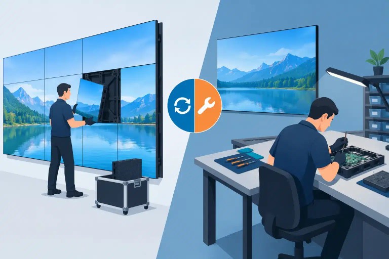
This is where repeated field swaps can become expensive. Replacing an entire module may restore the image, but it does not always identify whether the real cause was a failed driver IC, damaged PCB trace, cracked solder joint, hub-board fault, or improper previous repair. For valuable inventory or discontinued product lines, module-level and PCB-level repair can be a practical alternative to buying scarce replacements.
A qualified repair process should include incoming inspection, diagnosis, repair documentation, controlled reassembly, and final functional testing. For visual assets, final testing should evaluate more than whether pixels illuminate. Check color consistency, scan behavior, data stability, brightness response, and operation over an appropriate run time. A repair that looks acceptable for five minutes may require further evaluation before returning to a multi-day show or permanent installation.
Build a Repeatable Response for Time-Sensitive Failures
When a wall fails under schedule pressure, teams need a method that avoids guesswork. Keep known-good signal cables, spare receiving cards where appropriate, documented processor files, validated module samples, and a record of cabinet serial numbers or revisions. Label data paths during prep rather than trying to reconstruct them in a dark ballroom or arena loading dock.
For recurring failures, track the exact cabinet position, processor output, environmental condition, and symptom. If the same cabinet repeatedly fails in different positions, the cabinet should be bench-tested. If failures remain tied to one output or cable route, focus on that path. Trend data turns recurring downtime into a more actionable service decision.
With more than a decade of technical service experience supporting professional LED environments, 725Co. approaches these failures as system problems first and repair problems second. That means identifying the actual point of failure, performing precision repair when it is justified, and providing documented QC rather than treating every bad image as a reason to replace a panel.
The next time an LED wall presents a controller-like fault, resist the pressure to swap the most visible component first. Capture the pattern, verify each layer of the signal path, and preserve the evidence. That process creates a stronger technical basis for moving from temporary recovery toward an appropriate return to service.

Jose de Jesus Martinez (Chuy) is the CEO of 725co. LED Repair Professionals, a trusted name in high-quality LED module repair and video wall services. With over 12 years of experience and certification as an electronic engineer, Chuy has built a reputation for excellence, partnering with industry leaders. Under his leadership, 725co is known for precision repairs, transparent service, and a commitment to protecting the long-term value of LED investments.

6 Responses